Why?
Color coding your wiring helps with diagnosing. It forces you to think ahead of why you wire what, and in what way.
Types of wire purposes
There are multiple reasons you want to differentiate the types of wiring, as there are many purposes you’ll want to address on your layout. Here is an example;
- DC power
- Track power DC/DCC
- Switches
- Lighting
- Signals
An example of my requirements
In my case, I have the following requirements;
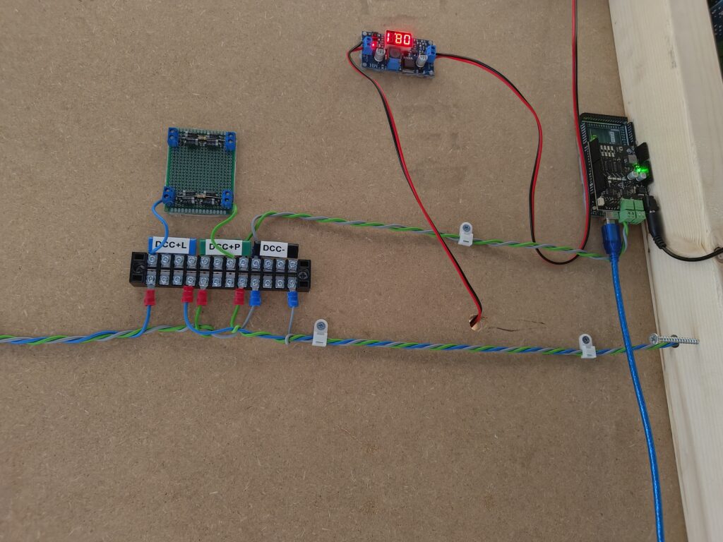
- DC power (realized by using a powersupply and buck converters per needed voltage) for example; 18v to my DCC controller, 12v for lighting, 9v for accessories like returnloop-boards)
- Lighting, 2 wires, +/- at 12v
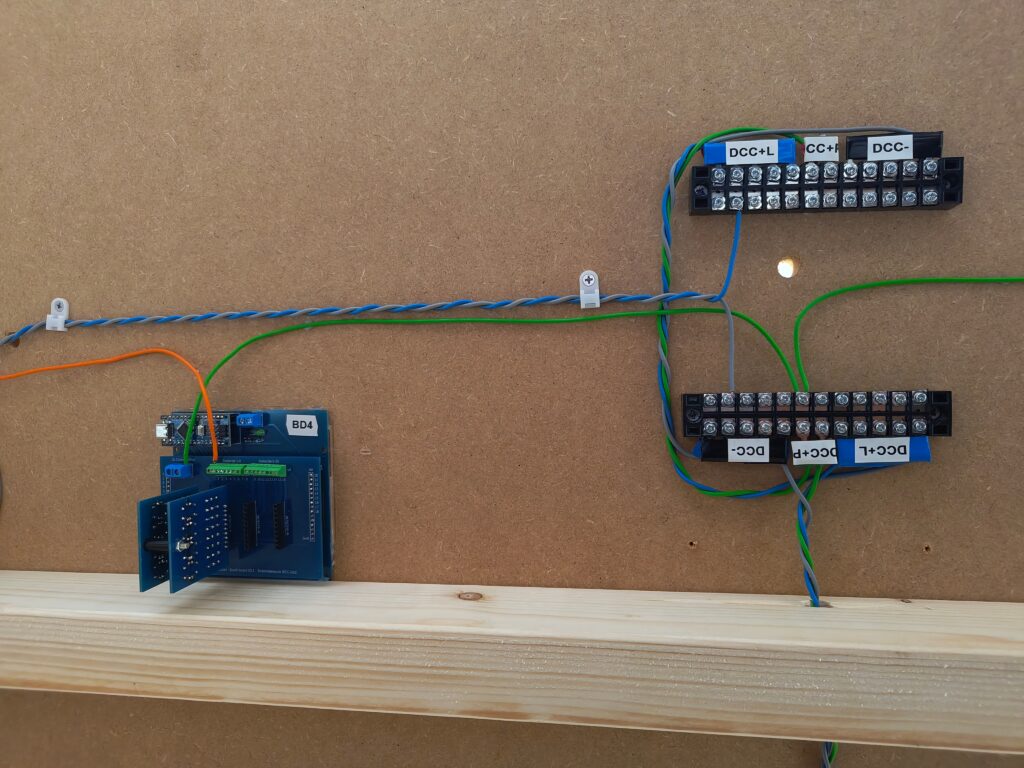
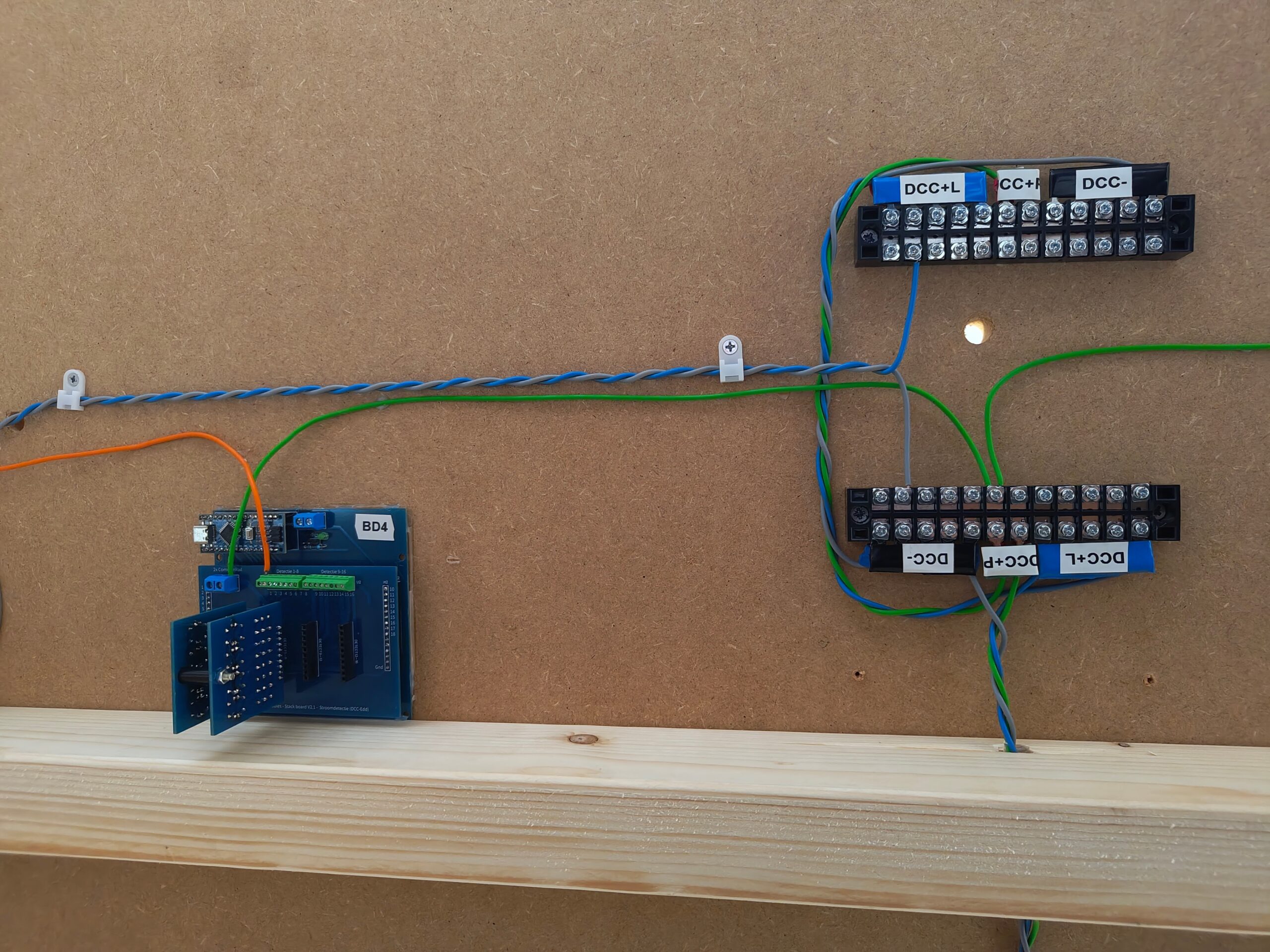
- DCC/track power, normally 2 wires will be enough, but in my case I have 3 for improved detection consistency (more on that in another post). 1 minus (common) wire, 2 plus (1 for the input on the current detection boards, and 1 directly to non-detecting tracks)
- Various, like wires between current detection boards and the detecting tracks, or between returnloop-boards and the corresponding tracks.
An example of the colors I use
- Red = DC power +
- Black = DC power +
- Yellow = Lighting +
- Brown = Lighting –
- Grey = DCC minus/common
- Green = DCC plus
- Blue = DCC plus, but fed by a diode circuit to lower the voltage to correspond with the current detection voltage, thus used for non-detecting tracks. Not needed if you’re not having reliability issues with detecting via currentsensing (octocouplers, etc).
- Orange = Detecting track power, thus between track and currentdetection-boards.


No responses yet